
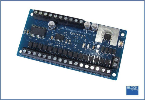
BLOCKsignalling PPI4-DC Points Position Indicator (PPI4 DC)
Advanced PPI with Adjustable Brightness & Simplified Wiring Monitors the brief positive operating voltage across points motors when they are switched Lights a corresponding led on a control panel to show the last operation of each set of points No resistors required for the leds (although any already wired in can remain) Saves all settings automatically to memory when the power is switched off Monitors up to 8 sets of points Opto-isolated inputs accept voltages from +5V to +60V Wiring up a model railway control panel to show points positions can be a daunting prospect. The BLOCKsignalling Points Position Indicator (PPI) monitors the brief switching voltage to either of the two coils of a points motor, and displays the last operation using coloured leds which can be mounted on a route mimic. Manual methods to switch points include simple spring-loaded switches, push buttons, probe and stud, etc and the points coils have a common connection to the ground of the supply. When points are driven from DCC Accessory decoders, the decoders most often provide a +12V supply to the common of the points coil, and then switch the other connections of the coils to ground to switch the points (use PPI2-DCC with these). This PPI is designed for operation on systems where the coil common is GROUND. The microprocessor controls the led brightness and so no resistors are required, simplifying wiring up. Any resistors already wired in series with the control panel leds can remain. Power Supply The controller is designed for use with a DC power supply of between 10V and 25V, or an AC power supply of between 10V and 16V. Higher voltages may damage the unit. Where there is a choice, the recommended power supply is 12V DC. Operation The PPI has 8 channels, each channel with two inputs able to drive two leds on the output. The inputs cause the associated output to switch when the input voltage rises above around 3V. Also, at this moment the other associated output is switched off. In this way, only one of the output leds is lit at any one time, that being the one with the most recent positive input voltage pulse. This means that only one of the route leds for each channel will be lit at any one time. Each time an input change occurs, it is stored in memory, so that when the power is switched off and on again, the led outputs are set automatically to their last recorded condition. For further instructions please visit this website: http://www.blocksignalling.co.uk/index.php/points-position-indicator-ppi4-dc
PPI4-DC